Buzzer Alarm Circuit Diagram. How this piezo buzzer circuit works ? Understanding some of the technologies and configurations of buzzers is useful during the design process, so in this blog post we will describe.

We will get the distance value using the equation above and after that, we will set a value which will help us make the buzzer high or low.
INTRODUCTION This is the second half of our Transistor Circuits e-book.
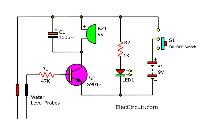
Simple high water level alarm circuit - ElecCircuit.com

Circuit: ANOTHER VERY LOUD PIEZO ALARM BEEPER __ Circuit ...
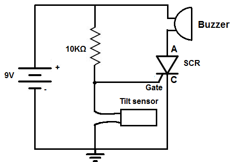
How to Build a Tilt Alarm Circuit
Motorcycle Alarm With Transistor Circuit Diagram | all ...
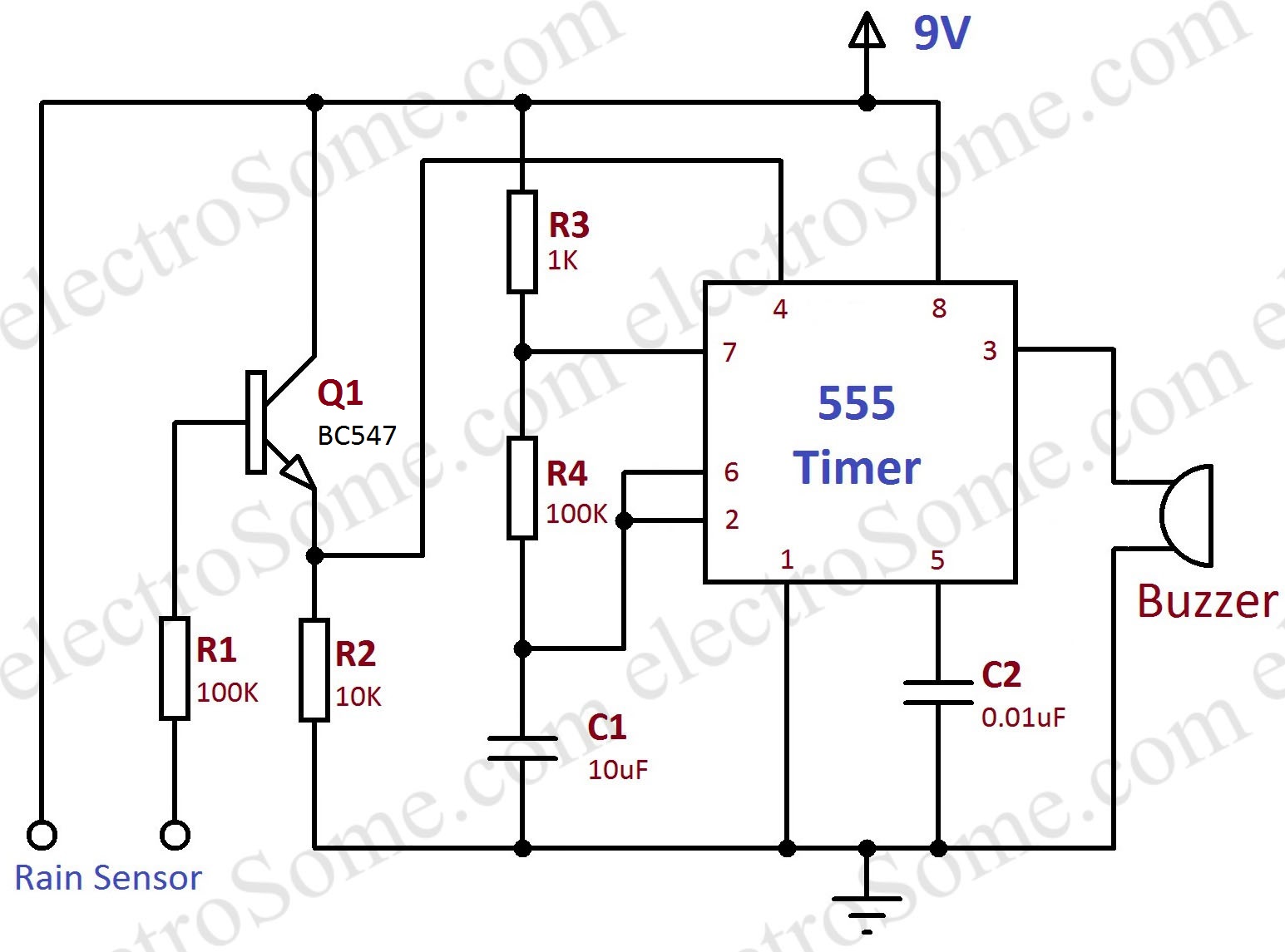
Rain Alarm using 555 Timer - Hobby Circuit
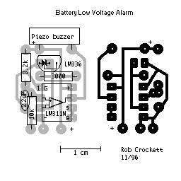
How to build Precision Receiver Battery Low Voltage Alarm ...
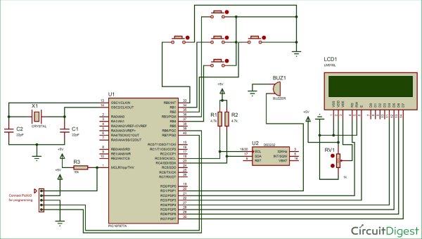
PIC16F877A Microcontroller Based Digital Alarm Clock

Burglar Alarm - Simple Electronics Project and Circuits

security door alarm circuit diagram
How this piezo buzzer circuit works ? Transistor gate open from emitter to collector and buzzer ring. Nowadays, all the householders/owners are storing the water in overhead tanks by using the pumps. of several different alarm circuits goes into an alarm state.
